- Table of contents
- U-Boot on the MitySOM-5CSX
- Branch Description
- Typical Environment Settings for DevKit
- Modification Summary
- Importance of Factory Configuration EEPROM
- Modifying Factory Configuration Data
- Below is a breakdown of the v1.2 I2C EEPROM (FT24C16A - 16Kbit) memory usage:
- Below is a breakdown of the v1.2 second MAC generic block I2C EEPROM (FT24C16A - 16Kbit) memory usage:
- Below is a breakdown of the v1.2 RTC calibration value generic block I2C EEPROM (FT24C16A - 16Kbit) memory usage:
- Deprecated - Below is a breakdown of the v1.3 I2C EEPROM (FT24C16A - 16Kbit) memory usage:
- Latest U-Boot Git SHAs for each factoryconfig version
- Building u-Boot and Preloader
U-Boot on the MitySOM-5CSX
git://support.criticallink.com/home/git/u-boot-socfpga.git
Please familiarize yourself with the Altera/Rocketboards port of u-boot described here
as the Critical Link MitySOM-5CSX port is based on the Rocketboards port, and many of the SocFPGA processor specifics are detailed on the Rocketboards wiki.
Branch Description
- socfpga_v2013.01.01 : Extensions to the rocketboards socfpga_v2013.01.01 branch (Altera ESDK 13.1)
- mityarm-5csx (deprecated): Extensions to the Rocketboards socfpga_v2012.10 branch (Altera ESDK 13.0sp1).
Typical Environment Settings for DevKit
The following u-Boot minimal environment settings / commands are necessary to utilize the full features of the DevKit Linux port. You'll need to add additional options to the bootargs to specify you're boot media.
Note For the Dev Boards with part numbers 80-000578RC-1 or -2 initphy should be set to "gpio set 48; gpio clear 48; sleep 1"
baudrate=57600
bootargs=console=ttyS0,57600
initphy=gpio clear 28; gpio set 28; sleep 1
initqspi=gpio set 35
bootcmd=run initqspi; run initphy; run mmcload; run mmcboot
bootdelay=5
bootimage=uImage
bootimagesize=0x600000
ethact=mii0
fdtaddr=0x00000100
fdtimage=mityarm-5csx.dtb
fdtimagesize=0x2000
fpga=0
fpgadata=0x2000000
fpgadatasize=0x700000
loadaddr=0x7fc0
micrel-ksz9021-clk-skew=0xa0d0
micrel-ksz9021-data-skew=0x0
mmcboot=setenv bootargs console=ttyS0,57600 root=${mmcroot} rw rootwait;bootm ${loadaddr} - ${fdtaddr}
mmcload=mmc rescan;${mmcloadcmd} mmc 0:${mmcloadpart} ${loadaddr} ${bootimage};${mmcloadcmd} mmc 0:${mmcloadpart} ${fdtaddr} ${fdtimage}
mmcloadcmd=fatload
mmcloadpart=1
mmcroot=/dev/mmcblk0p2
stderr=serial
stdin=serial
stdout=serial
Modification Summary
The following general extensions have been added to the basic u-Boot image from Rocketboards:
- Added support for the CL factoryconfig command.
- Added I2C support (to support factoryconfig) [ back port 2013 designware_i2c driver ]
- Added support for quadspi NOR device
- Added HPS GPIO command support
Importance of Factory Configuration EEPROM
The MLO is dependent on a proper load of factory configuration data on the on-board I2C EEPROM. The factory configuration data include the serial number, model number, a version number, and a checksum. Additional configuration is stored in generic blocks that include the data type and size, the data itself, and a checksum. At this time generic blocks for a second MAC address and an RTC calibration value are supported. You can inspect and modify (though you should not need to do this) the factory configuration data using the u-Boot "factoryconfig" command provided with CL ported u-Boot code.
Under the new mitysom-5csx branch, the u-Boot MLO (preloader) will read the CL model number from the I2C factory configuration I2C EEPROM at start up. The device MAC address and serial number are also stored in the factory config EEPROM. Generic blocks are stored in the factory config EEPROM as well, immediately following the base factory config.
Modifying Factory Configuration Data
In most cases it is not recommended to change any information in the EEPROM but for certain causes such as filling in the 2nd MAC address the following steps can be used to do so.
- Power on the unit.
- In U-Boot, when you see "Hit any key to stop autoboot:" and a countdown, type a key to break into U-Boot.
- At the prompt, type the command
factoryconfig setand press enter. - Update each field as necessary, pressing enter to move to the next field.
- At the prompt, type the command
factoryconfig saveand press enter. This is what actually writes the new config to the EEPROM. - Type the command
resetand press enter to reboot the unit with the new factory config.
Below is a breakdown of the v1.2 I2C EEPROM (FT24C16A - 16Kbit) memory usage:
u-boot-socfpga.git/board/cl/mityarm-5csx/config_block.h

u32               ConfigMagicWord;  /** CONFIG_I2C_MAGIC_WORD */
u32               ConfigVersion;    /** CONFIG_I2C_VERSION */
u8                MACADDR[6];
u32               FpgaType;
u32               Spare;            /** Not Used */
u32               SerialNumber;     /** serial number assigned to part */
char              ModelNumber[32];   /** board model number, human readable text, NULL terminated */
Below is a breakdown of the v1.2 second MAC generic block I2C EEPROM (FT24C16A - 16Kbit) memory usage:
u-boot-socfpga.git/board/cl/mityarm-5csx/config_block.h

u32 MagicWord;
u16 Type;
u16 Size;
u8 MacAddress[6];
How To Manually Add Second MAC to Factory Config
Below is a breakdown of the v1.2 RTC calibration value generic block I2C EEPROM (FT24C16A - 16Kbit) memory usage:
u-boot-socfpga.git/board/cl/mityarm-5csx/config_block.h

u32 MagicWord;
u16 Type;
u16 Size;
s32 RtcCalVal; /* PPM * 10 to allow for signal decimal percision */
Deprecated - Below is a breakdown of the v1.3 I2C EEPROM (FT24C16A - 16Kbit) memory usage:
u-boot-socfpga.git/board/cl/mityarm-5csx/config_block.h

u32               ConfigMagicWord;  /** CONFIG_I2C_MAGIC_WORD */
u32               ConfigVersion;    /** CONFIG_I2C_VERSION */
u8                MACADDR[6];
u32               FpgaType;
u32               Spare;            /** Not Used */
u32               SerialNumber;     /** serial number assigned to part */
char              ModelNumber[32];   /** board model number, human readable text, NULL terminated */
u8                MACADDR2[6];      /** Default to 0.. Contact Critical Link for allocation of second MAC if both MACs used */
Latest U-Boot Git SHAs for each factoryconfig version
| v1.2 with no generic blocks | aedd49cd36ee44f289def36aabc9f1c7a1686342 |
| v1.3 | 74ce7627af326a7a069be67e598a9dfb279f98b3 |
| v1.2 with 2nd MAC generic block | b1ed50949ee11bf43d19035003a37eaf281e6b23 |
| v1.2 with 2nd MAC and RTC calibration value generic blocks (current) | afd82661f4ecba146d24a1e3ef1b4b94a85718ac |
Building u-Boot and Preloader
Preparing a new SD card
The Altera preloader wiki site has information on building an SD card that is bootable and contains a linux filesystem.
There are also some details on our Starter guide wiki page

Booting from Quad-SPI NOR flash
One of the boot modes supported by the MitySOM-5CSX is to boot from Quad-SPI NOR flash. There can be 0MB, 16MB, 32MB, 48MB or possibly more NOR flash installed on the module (order option).
To boot from quad SPI flash, set the boot mode to 0x6 (110). Do NOT set the boot mode to 0x7 as the QSPI part on the SOM is a 1.8V device, and boot mode 7 is for a 3V device!
You can use U-Boot to program or update the boot and/or application image(s) within QSPI flash:
- Transfer file to memory on module to then be written to the NOR memory by one of the 3 methods below
- You can store you files into FAT partition of a SDMMC. This can be done by just copying files onto it from a PC onto the card and then inserting it into your development kit or carrier board after the unit has entered UBoot.
- Stop the boot process in u-boot and load the file from the SDMMC.
MitySOM-5CSX # mmc rescan
MitySOM-5CSX # fatload mmc 0:1 2000000 <filename>
- Stop the boot process in u-boot and load the file from the SDMMC.
- Stop the boot process in u-boot and load the file from a TFTP server.
MitySOM-5CSX # tftp 2000000 myserver:/path/to/<filename>
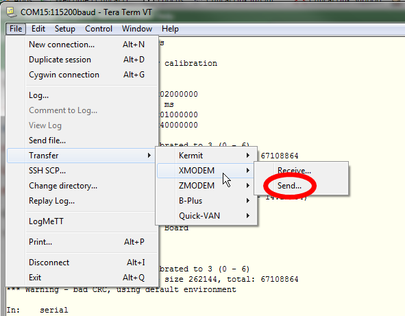
- Stop the boot process in u-boot and load the file from the serial port using YModem.
- load DTB over serial line
MitySOM-5CSX # loady 2000000
- Send DTB using YMODEM

- Select your file
- Example output in u-boot terminal...
### Ready for binary (ymodem) download to 0x00020000 at 115200 bps...
CCxyzModem - CRC mode, 158(SOH)/0(STX)/0(CAN) packets, 6 retries
### Total Size      = 0x00004e60 = 20064 Bytes
- load DTB over serial line
- You can store you files into FAT partition of a SDMMC. This can be done by just copying files onto it from a PC onto the card and then inserting it into your development kit or carrier board after the unit has entered UBoot.
- Erase the flash memory area you wish to program into
MitySOM-5CSX # sf probe 0
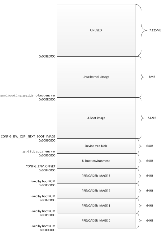
MitySOM-5CSX # sf erase 0     40000 [for preloader]
MitySOM-5CSX # sf erase 50000 10000 [for DTB]
MitySOM-5CSX # sf erase 60000 80000 [for U-Boot]
MitySOM-5CSX # sf erase E0000 xxxxx [for uImage (linux kernel)]
- Program the file into the flash memory
MitySOM-5CSX # sf write 2000000 0     $filesize [for preloader]
MitySOM-5CSX # sf write 2000000 50000 $filesize [for DTB]
MitySOM-5CSX # sf write 2000000 60000 $filesize [for U-Boot]
MitySOM-5CSX # sf write 2000000 E0000 $filesize [for uImage (linux kernel)]
First (CS0) Bootable NOR Flash Memory Map

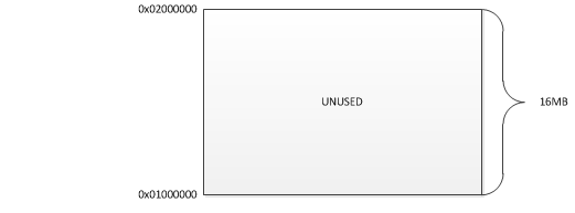
Second (CS1) Bootable NOR Flash Memory Map

Note that for modules with 32MB for the second NOR flash memory (48MB total on module) that the start address for the second memory is still 0x0100000 and ends at 0x03000000. All memory space is available for user files.
Updated over 3 years ago by Jonathan Cormier
Go to top

