Linux Audio Support
Audio support for linux is based on the Linux for Qualcomm Software support.
Development Board Configuration
Power
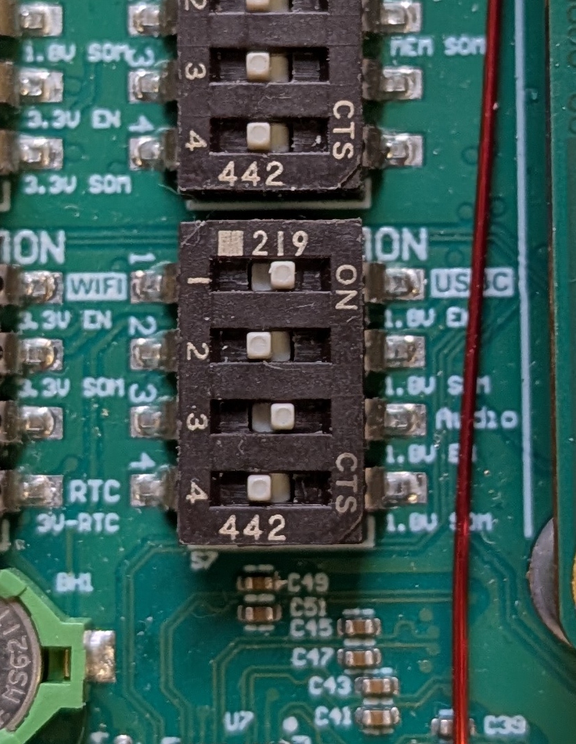
Ensure that Switch S7 is set properly to power the SGTL5000 Codec chip:- Switch 3 should be set to enable Audio, which is a top level enable to send 1.8 V to the audio codec chip SGTL5000XNBA3 (U16).
- Switch 4 can be either set or not set
- If Switch 4 is not set the 1.8V comes from the DC supply on the Development Kit
- If Switch 4 is set the 1.8V comes from the SOM
Audio Interface Options
There are two available interfaces for audio input/output:
- The J8 AUDIO 3.5 mm jack that supports stereo headset with mono microphone:
- The J23 LINEIN/LINEOUT Header
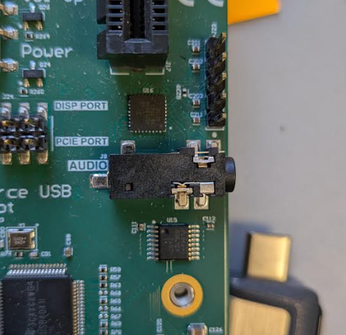

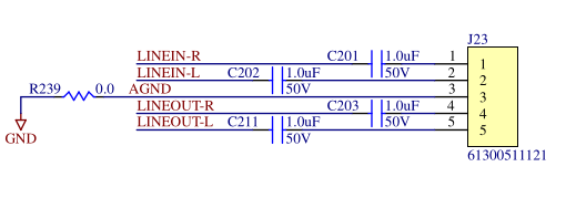
Headset Examples
This section details how to validate AUDIO jack J8.
Configuration
The following steps will configure the SGTL5000 Codec chip to utilize the Headset for input and output.
# Set Playback volume high so it can be heard
tinymix set 'PCM Playback Volume' 160 160

# Set capture volume high so we can hear what we capture
tinymix set 'Capture Volume' 15 15

# Capture is quiet enough, don't further attentuate
tinymix set 'Capture Attenuate Switch (-6dB)' 0

# Enable Zero Crossing capture switch to minimize popping
tinymix set 'Capture ZC Switch' 1

# Enable Capture switch so we can record audio input
tinymix set 'Capture Switch' 1

# Set Headphone playback volume to halfway so its loud enough to be heard clearly
tinymix set 'Headphone Playback Volume' 63 63

# Enable headphone playback
tinymix set 'Headphone Playback Switch' 1

# Enable headphone zero crossing switch to limit popping
tinymix set 'Headphone Playback ZC Switch' 1

# Increase mic volume since recordings are always so quiet
tinymix set 'Mic Volume' 2

# Select MIC_IN for capture
tinymix set 'Capture Mux' 0

# Select DAC as output for Headphones
tinymix set 'Headphone Mux' 0

# Select I2S for what feeds into DAC for output (skip DAP)
tinymix set 'Digital Input Mux' 1
Headphones Audio Out
Below are a number of examples of how to play audio:- Play 400 Hz tone in stereo
gst-launch-1.0 audiotestsrc ! audioconvert ! audio/x-raw,channels=2 ! alsasink
- Play 400 Hz tone left channel only
gst-launch-1.0 audiotestsrc ! audiochannelmix left-to-left=1 right-to-left=1 right-to-right=0 ! alsasink
- Play 400 Hz tone right channel only
gst-launch-1.0 audiotestsrc ! audiochannelmix left-to-left=0 left-to-right=1 right-to-right=1 ! alsasink
- Play .wav file (see attachement) with vumeter
paplay LRMonoPhase4.wav -v
Recording Headset Mic Audio
Below is an example of recording audio with an active vumeter to indicate intensity of audio being recorded:
arecord -f dat --vumeter=mono test_mic.wav
LINEIN/LINEOUT Examples
This section details how to validate LINEIN/LINEOUT header J23.
Configuration
The following steps will configure the SGTL5000 Codec chip to utilize LINEIN and LINEOUT.
# Set Playback volume high so it can be heard
tinymix set 'PCM Playback Volume' 160 160

# Set capture volume high so we can hear what we capture
tinymix set 'Capture Volume' 15 15

# Capture is quiet enough, don't further attentuate
tinymix set 'Capture Attenuate Switch (-6dB)' 0

# Enable Zero Crossing capture switch to minimize popping
tinymix set 'Capture ZC Switch' 1

# Enable Capture switch so we can record audio input
tinymix set 'Capture Switch' 1

# Set line out playback to halfway so it's loud enough to be heard clearly
tinymix set 'Lineout Playback Volume' 15 15

# Enable Line out
tinymix set 'Lineout Playback Switch' 1

# Select LINE_IN for capture
tinymix set 'Capture Mux' 1

# Select I2S for what feeds into DAC for output (skip DAP)
tinymix set 'Digital Input Mux' 1
LINEOUT Audio Out
Follow steps in Headphones Audio Out
Recording LINEIN Audio
Follow steps in Recording Headset Mic Audio
Additional Details
The following sections provide additional details regarding audio in the MitySOM-QC Development Kit.
Hardware Overview
A hardware block diagram of the audio subsystem is shown below. The following components are involved on the MitySOM-QC6490 devkit:
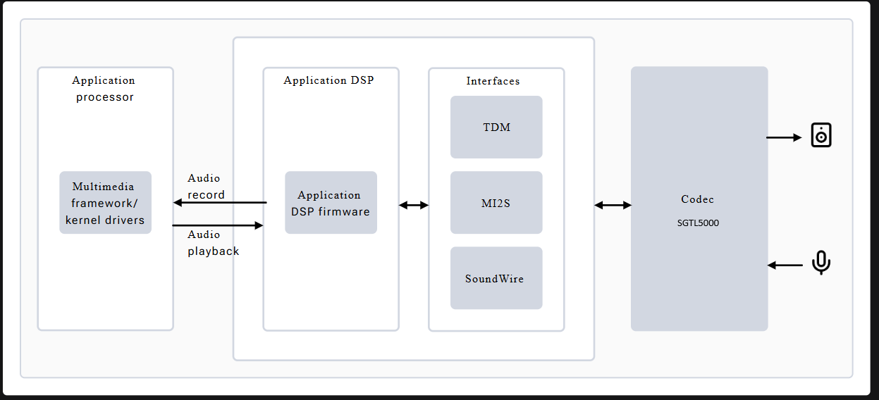
- Application processor – This is the ARM CPU complex and handles audio processing tasks, including:
- Managing audio record and playback
- Decoding audio formats
- Using LPAI for postprocessing tasks
- Low Power AI (LPAI) – Subsystem that runs audio playback/record and voice-activation (VA) algorithms. It integrates with a dedicated Qualcomm® Hexagon™ Processor (QDSP6) and a low power island (LPI).
- Audio codec – For the devkit this is a SGTL5000 and it is connected to the LPAI via I2S0 connections. It provides:
- Analog-to-Digital Converter (ADC) for capturing microphone / line-in signals and converting them to I2S
- Digital-to-Analog Converter (DAC) for converting stereo I2S data to analog outptus for either the Headphones or line-out signals
- Headphone / Mic Jack
Additional information can be found on Qualcomm's Audio Overview page
SGTL5000 CODEC and Controls
The linux SGTL5000 codec driver includes several controls for the routing and data within the SGTL5000 chip (between the jacks and the I2S0 bus). A top level block diagram of the SGTL5000 is shown below:
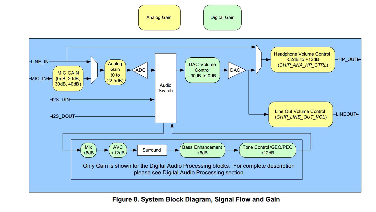
From the picture, the 3 signal audio jack is connected to the Headphone outputs (stereo) and microphone inputs (mono) for use with a standard analog headset with microphone. The line in and line out signals are routed to the expansion header J23. By default, playback commands will be routed to the HeadPhone interface and capture commands will capture from the microphone input.
The available controls of the output SGTL5000 codec can be listed (along with their settings) with the tinymix command as shown below.
root@qcs6490-mitysom-devkit:~# tinymix contents
Number of controls: 28
ctl     type    num     name                                            device  value
0       INT     2       PCM Playback Volume                             0144, 144 (range 0->192)
1       INT     2       Capture Volume                                  012, 12 (range 0->15)
2       BOOL    1       Capture Attenuate Switch (-6dB)                 0Off
3       BOOL    1       Capture ZC Switch                               0On
4       BOOL    1       Capture Switch                                  0On
5       INT     2       Headphone Playback Volume                       0110, 110 (range 0->127)
6       BOOL    1       Headphone Playback Switch                       0On
7       BOOL    1       Headphone Playback ZC Switch                    0On
8       INT     1       Mic Volume                                      00 (range 0->3)
9       INT     2       Lineout Playback Volume                         016, 16 (range 0->31)
10      BOOL    1       Lineout Playback Switch                         0Off
11      INT     1       DAP Main channel                                032768 (range 0->65535)
12      INT     1       DAP Mix channel                                 00 (range 0->65535)
13      BOOL    1       AVC Switch                                      0Off
14      BOOL    1       AVC Hard Limiter Switch                         0Off
15      INT     1       AVC Max Gain Volume                             01 (range 0->2)
16      INT     1       AVC Integrator Response                         01 (range 0->3)
17      INT     1       AVC Threshold Volume                            012 (range 0->96)
18      INT     1       BASS 0                                          047 (range 0->95)
19      INT     1       BASS 1                                          047 (range 0->95)
20      INT     1       BASS 2                                          047 (range 0->95)
21      INT     1       BASS 3                                          047 (range 0->95)
22      INT     1       BASS 4                                          047 (range 0->95)
23      ENUM    1       Capture Mux                                     0> MIC_IN, LINE_IN,
24      ENUM    1       Headphone Mux                                   0> DAC, LINE_IN,
25      ENUM    1       Digital Input Mux                               0ADC, > I2S, Rsvrd, DAP,
26      ENUM    1       DAP Mux                                         0> ADC, I2S,
27      ENUM    1       DAP MIX Mux                                     0> ADC, I2S,
Note: the tinymix command does not put a space between the device number (always "0" in this case) and the settings.
In this case, the 'PCM Playback Volume' represents the digital DAC Volume Control, the 'Headphone Playback Volume' represents the analog gain on the Headphone volume control, the 'Capture Volume' represents the Analog Gain block entering the ADC, and the 'Mic Volume' represents the MIC GAIN block.
The tinymix tool can be used to adjust these settings. For example, to increase the analog output volume of the headphones channel:
tinymix set 'Headphone Playback Volume' 120 120
This will set both the left and right channel gain setting to be "120".
Below is the same top level diagram (shown above) for the SGTL5000 codec with some of the tinymux control names added for clarity:
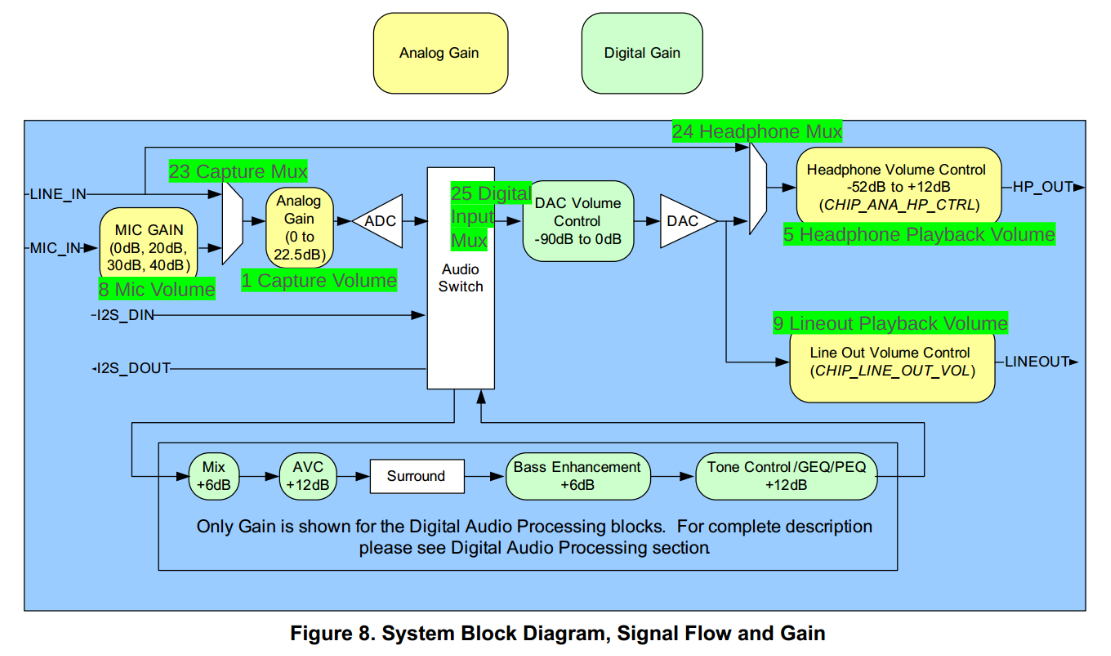
There are other features of the codec not discussed here (including routing the audio through the Digital Audio Processor(DAP)) that can be leveraged in a similar manner.
See the SGTL5000 Datasheet for further details.