- Table of contents
- Objective
- Prerequisites
- Steps
- Controlling GPIOs using Legacy Sysfs (Alternative)
- Physical Verification with a Multimeter
- Summary
Objective
The objective of this example is to show how to locate, configure, and control an unused GPIO from user space on the MitySOM-AM62 development kit.
Prerequisites
- Development Kit Schematic. See MitySOM-AM62_Development_Kit
- Linux Kernel Source Code. See Linux_Kernel
Steps
Picking a GPIO to use
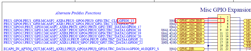
Most pins on the development kit's expansion connectors have multiplexed functions. The actual function of a physical pin is determined by how its PinMux is configured in the Linux device tree.For this example, we will use Pin 3 on the P3 Expansion Header:
- Schematic Label:
GPMC_AD0_BM0 - Alternate Function needed:
GPIO0_15 - Physical Processor Ball:
M25
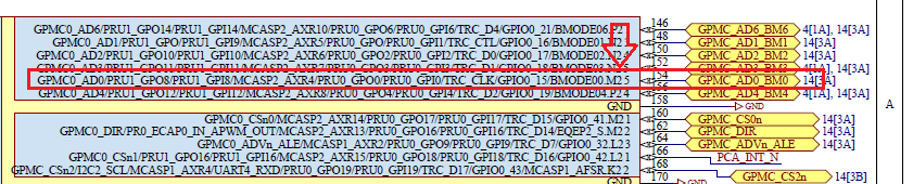
Looking at the schematics, we can verify the information above for our desired pin of choice.
On Page 14 of the schematic:
On Page 3 of the schematic:
Verifying that Pinmux
Before using a pin as a GPIO, verify it is multiplexed correctly in the device tree. In the kernel source code file arch/arm64/boot/dts/ti/k3-am62x-mitysom-devkit.dts, you will find the GPIO configuration under the main_gpio_p3_pins_default node.
    main_gpio_p3_pins_default: gpio-p3-pins-default {
        pinctrl-single,pins = <
            /* P3 Connector */
            AM62X_IOPAD(0x003c, PIN_INPUT_PULLDOWN, 7) /* (M25) GPMC0_AD0.GPIO0_15 */
            AM62X_IOPAD(0x0040, PIN_INPUT_PULLDOWN, 7) /* (N23) GPMC0_AD1.GPIO0_16 */
            AM62X_IOPAD(0x0044, PIN_INPUT_PULLDOWN, 7) /* (N24) GPMC0_AD2.GPIO0_17 */
            AM62X_IOPAD(0x0048, PIN_INPUT_PULLDOWN, 7) /* (N25) GPMC0_AD3.GPIO0_18 */
            AM62X_IOPAD(0x004c, PIN_INPUT_PULLDOWN, 7) /* (P24) GPMC0_AD4.GPIO0_19 */
The '7' at the end of the AM62X_IOPAD macro configures the pin to Mode 7, which corresponds to GPIO0_15.
If the function was set to something else, you can follow the instructions in https://support.criticallink.com/redmine/projects/mitysom_am62x/wiki/Linux_Kernel_Setup_Pinmux to set the line for GPIO0_15.
Understanding GPIO Line Names
The Linux kernel popilates gpio-line-names in the device tree (.dtsi). This assigns human-readable strings like "GPIO0_15" directly to the hardware pins, allowing user-space tools to interact with them by name instead of magic numbers. If you build a custom baseboard, you can overwrite these names in your top-level board .dts file.
Critical Link GPIO Tool (Recommended)
For convenience, Critical Link provides lightweight wrapper utilities pre-installed on our filesystem images to simplify line-name access:
# Set GPIO0_15 to an output driven HIGH
gpio GPIO0_15 set 1

# Read the value back
gpio GPIO0_15 get
Note: Critical Link's GPIO helper tool uses the deprecated sysfs interface (/sys/class/gpio)
Controlling GPIOs using libgpiod/gpiod
Modern Linux distros deprecate the older /sys/class/gpio interface in favor of libgpiod. Depending on your filesystem image version, you will have either v1.6 or v2.0+ tools installed.
Using libgpiod v2.0+
Newer images allow you to interact with the GPIO directly using its device-tree name, completely eliminating the need to look up chip indices or base offsets. Note: in libgpiod v2.0+, a GPIO line state is only maintained while the gpioset process is actively running. If the command exits or is killed, the pin reverts to its default hardware state. To drive the pin indefinitely, use the --daemonize flag, or to hold it for a specific duration, use the --hold-period flag.
- Set the pin as the output and drive it HIGH (1):
gpioset GPIO0_15=1
- Drive the pin LOW (0):
gpioset GPIO0_15=0
- Read the current state of a pin:
$ gpioget GPIO0_15
"GPIO0_15"=active
activecorresponds to a high state (3.3V), whileinactivecorresponds to a low state (0V)
Using legacy libgpiod (v1.6)
If your system utilizes older gpiod utilities, you must first resolve the line name to its explicit hardware chip and line offset using gpiofind.
- Find the hardware mappings:
$ gpiofind GPIO0_15
gpiochip2 15
- Drive the pin HIGH (1) or LOW (0):
gpioset gpiochip2 15=1
gpioset gpiochip2 15=0
- Read the pin status:
gpioget gpiochip2 15
Controlling GPIOs using Legacy Sysfs (Alternative)
If your application requires the legacy Linux sysfs interface (/sys/class/gpio), you must calculate the global Linux GPIO integer identifier.
Quickly Finding the sysfs GPIO Number
Instead of tedious cross-referencing, you can grep the kernel debug filesystem directly to map the line name to its sysfs index:
root@mitysom-am62x:~# grep "GPIO0_15" /sys/kernel/debug/gpio
gpio-409 (GPIO0_15        |sysfs        ) in hi
Exporting and Controlling the Pin
- Export the GPIO to user-space:
echo 409 > /sys/class/gpio/export
- This generates a new control directory at /sys/class/gpio/gpio409
- Set the direction to output
echo out > /sys/class/gpio/gpio409/direction
- Toggle the value
echo 1 > /sys/class/gpio/gpio409/value
echo 0 > /sys/class/gpio/gpio409/value
- Unexport the GPIO when finished
echo 409 > /sys/class/gpio/unexport
Physical Verification with a Multimeter
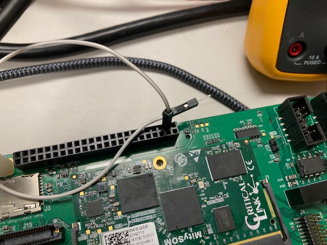
To visually/electrically confirm the software commands are working as intended:- Insert a smalle lead wire into Hole 3 of the P3 connector (odd-numbered holes run along the outer edge of the connector block).
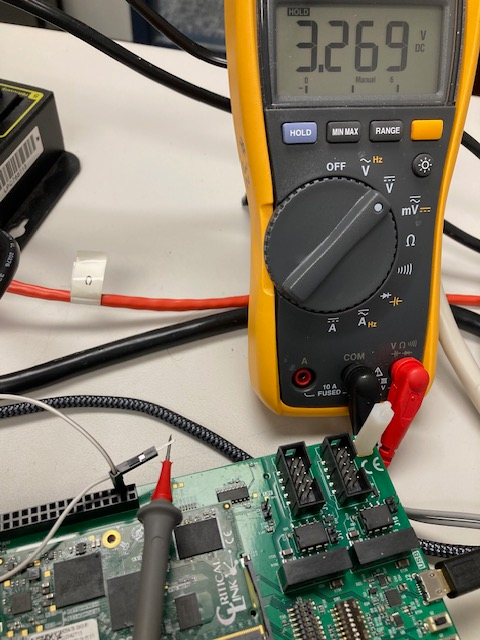
- Set your multimeter to DC voltage. Place the black (ground) probe on a designated ground test point (e.g., TP19) and the red probe on the lead wire.
- Toggle the GPIO state between 1 (3.3V) and 0 (0V) using any of the methods listed above to observe the voltage shift.
Location of Hole 3 on the P3 connector:
Multimeter showing level when value of GPIO is 1:
Summary
This example has shown how to:
- Identify a GPIO to use
- Determine the Linux GPIO number for the GPIO
- Make the GPIO available as part of the /sys/class/gpio directory
- Use user-level commands to set the direction and value of the GPIO
- Remove the GPIO from the /sys/class/gpio directory
- Physically verify GPIO state
Go to top

